|
by
David Barron
For better than 20
years, I have built or helped build several model railroad electrical control
panels. At first, these ended up very simple; later ones ended up
somewhat more complicated. During my
latest venture, I wanted to install something with a little more zing, and yet
foolproof, simple, and inexpensive. The
thought of having illuminated turnout position indicators allows you to tell at
a glance if you are lined up or not. The
idea of having this illumination, rather than toggle switch position, appeals to
everyone.
Several commercial
illuminated switches have been offered, which at times were mechanical
nightmares or complicated wiring nests. If
anything ever went wrong, as it always eventually does, simplicity is a must. Light emitting diodes (LEDS) seem to be the answer. The following circuit will work with any system that requires a constant
power supply to the switch machine (i.e., Tortoise by Circuitron -- not solenoid
or momentary contact circuits).
Figure 1 shows the
minimum components required for this circuit; for each indication required they
include 1 1K Watt Resistor and 2 colored LEDS, the colors are your
choice. Optional pairs would include
1 plastic LED holder per LED in the control panel. All of these parts are readily available at all electronics
stores, including Radio Shack, or your local hobby shop by Miniatronics. Miniatronics has an 18 pieces set of red, yellow, and green LEDS with
resistors all in a single package (Model 12-050-18) for about $7.50. That is enough to do at least 5 position indicators and have some parts
left over.
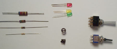
Figure
1. Components for circuit.
My requirement was to
color code the LEDS so that Green would indicate the switch was set for
the main line operations and Yellow would indicate the switch was set for
the siding. A quick glance at the control panel was all that was needed
to tell if all switches were properly aligned prior to main line or Green
Light operations.
Here's a quick note
or explanation as to the functions of these two simple components for those who
are unfamiliar with them. Resistors
come in many sizes and shapes but they all do the same basic thing, they limit
current. They operate like a funnel and only allow so much current to
flow through at a time. They are
color coded with different bands of color to indicate their different
restricting values. You can consult
any electronic book for your favorite memory code jogger, or visit http://www.dannyg.com/examples/res2/resistor.htm
for a Resistor Calculator.
Diodes also come in many sizes and shapes. They also come under different names depending on their
function, the ones that we want are known as Light-Emitting Diodes, LEDS.
These come in three basic colors: Red, Green, and Yellow.
An LED works, or lights, when a current passes through it in one
direction only. That is the way a
diode works, it only allows current to pass thorough it in one direction and not
the other way. Kind of like a one
way check valve. By positioning the
LED the way we want we can control its function much like a one way
electrical valve and see the valve position.
The reason we are
using a resistor in this circuit is that we are using the 12 volt DC poser
supply common with most power packs. We
want to drop the power down to a value that will not damage the LEDS.
The LEDS are used in opposing positions so that as we change the current
polarity, by throwing the toggle, we reverse the current through the LEDS, so it
cannot go through the lighted LED anymore but it now goes through the LED not
previously illuminated.
Although there are
exceptions to every rule, I have never found an LED that didn't have one long
leg and one short leg. The proper
names are the cathode lead and the anode lead, but I'll refer to them as the
short and long legs. There are a
few things that you must remember in order to correctly get this circuit
working. First NEVER attach the LED directly to power without the
dropping resistor or it will go pop and like a match it won't work a
second time. The second thing is that these LEDS must operate opposite of
each other or they will both light together or go out together, not what we are
looking for. Lastly, use heat
sparingly as excess heat when soldering can damage the components.
If you are using a
double pole, double throw (DPDT) toggle switch, wired up as Linn Westcott
indicates in his book, How to Wire Your Model Railroad, to reverse
current, then this circuit can easily be added to your existing system.
Figure 3 shows how the back of the DPDT Toggle should be wired.
Now, Let's get
started. Figure 2 shows the basic
circuit that we are about to put together.
First, locate where you can't the LEDS located on your control panel.
I put mine next to the respective toggle switches in a vertical line.
This allows me to take a quick glance down at them to make sure
everything is lined up. After
drilling the appropriate holes in your control panel, (I found that a Masonite
hard board is perfect for the job), you can either glue the LEDS directly in
place or use the special plastic snap clips to mount them in.
I like the plastic clips in that it leaves a nice finished black ring
around the LEDS when viewed from the top and it makes them easy to replace
should you have to. Now, solder
either end of the 1K Watt Resistor lead to point A on the toggle and
the other end the short leg on one LED and long leg on the other
LED. Next, solder one end of the wire
to point B on the toggle and the other end to the remaining two LED legs.
Turn your switch machine power on and you should have one LED lit and the
other one off. Flip the Toggle and
the lit LEDS should switch illuminated positions.
If the LEDS both go on or off, at the same time when you flip the toggle
switch, you simply have one in backwards. Unsolder
one and turn it around and test it again.
Figure
2. Double pole double throw toggle switch.
What's
the advantage of this system over the other systems?
It saves a lot of time and excess wiring from the toggle to the switch
machine. For those individuals who will say this system doesn't show
the position of the switch machine or points, I answer by simply saying, on a
correctly wired and operating system, this is easier to understand and the
control panel indication end results are the same. In reality, it is a visual indication of the switch position
rather than turnout position, but the switch controls the turnout, so all is
good. The only time the lights and
the turnout would be out of sync would be during a malfunction.
Other than that, this is a positive, simple, and inexpensive turnout
position indicator.
Click
ARTICLES to read other techniques for model railroading. |